¶ 2.1. IoT ARCHITECTURE
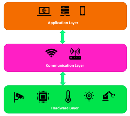
IoT technologies are used by people for the benefits and services they provide. Although there are many benefits provided by IoT technologies , there are also some difficulties such as management, energy efficiency, security and privacy. At the same time, IoT devices generate a large amount of data during use. Due to the difficulties in managing the large amount of data and the use of IoT technology, stratified models have been required. These models are called architectures. In particular, the Internet of Things is a structure that expresses the architecture, physical components, network organization and settings, administrative operations, and the type of data to be used. However, since IoT systems are a technology that covers many different technologies, there is no single standardized architecture for IoT . While a 3-tier architecture is used in basic and common IoT systems, 4, 5 or 7-tier architectures can also be used in more specialized IoT systems. Each layer within the architecture is often used for administrators to evaluate the consistency of the IoT system, maintain its monitoring, and facilitate its management. Figure 2.1 shows the 3-layer IoT architecture.
¶ 2.1.1. Hardware Layer
This layer is the physical layer of the IoT system. This layer contains sensors, devices and connected ports. In this layer, data is collected through sensors according to the needs of the system.
¶ 2.1.2. Communication Layer
In this layer, the transmission of the data collected in the hardware layer is carried out. Connecting devices to other sensors (nodes), servers and network devices and transmitting data are done in this layer.
¶ 2.1.3. Application Layer
application layer is the layer where users communicate with IoT systems. Customized software is run in this layer for users to use, monitor and manage the IoT system. By providing access to IoT sensors or devices , the software both transmits the user's requests to the application layer and may not provide the data from the application layer to be interpreted and displayed.
¶ 2.2. IoT COMPONENTS
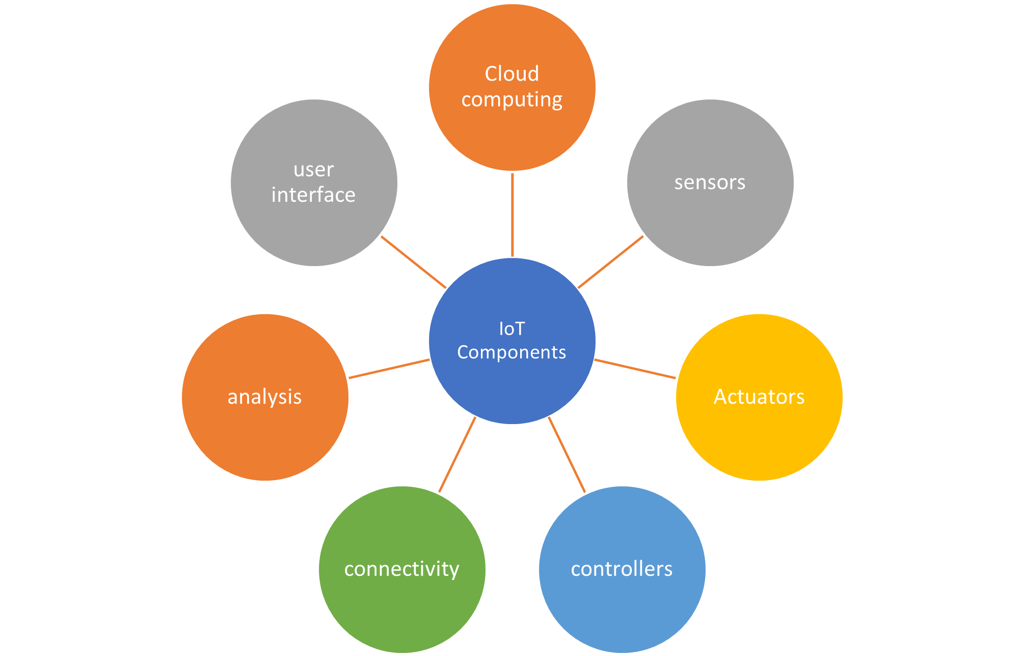
There are many different types of IoT devices. Most of these devices use controller (controller), sensor and actuator (actuator) components to perform their functions. Events, changes and physical size data in the environment are detected and sent to the controller in real time through the sensors in the IoT device. The controller analyzes and processes this data. If the data is too large for the controller to process, it can be sent to the cloud for processing. The controller uses actuators to perform actions after the data has been processed. This process is repeated continuously (Figure 2.2).
¶ 2.2.1. sensors
A sensor is a device that produces quantitative data that is used to measure an environmental feature by detecting some kind of information in the environment. This detected information; It can be light, humidity, distance, motion, pressure, speed, temperature, slope, or some other environmental feature. Sensors are like the sense organs of the system. Different environmental features that need to be detected require different types of sensors. Sensors are available in two types, analog and digital. The sensors are wired or wirelessly connected to the controller. The sensors send the data to the controller for analysis and decision making.
According to the output type, the sensors are examined in three groups.
- Analog Sensors: These are the structures that continuously read the values such as light, temperature, humidity, sound, wind intensity in the external environment and return this information as a voltage value between certain values.
- Digital Sensors: They are structures that continuously read values such as light, temperature, humidity, sound, wind intensity in the external environment and return this information in binary number system.
- Both Analog and Digital Sensors: While displaying the values read from the external environment as voltage over 1 pin, at the same time, if the measurement made according to a specified threshold value is above the threshold value, it is logic 0; They are structures that return logic 1 if the measurement is below the threshold value.
¶ 2.2.1.1. Temperature Sensor
They are the elements that measure the temperature value in the outdoor environment and output analog or digital.
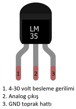
The most obvious sensor, which can be an example of sensors that give analog output, is the LM35. When the document of the LM35 sensor is examined, it is observed that this sensor can operate at voltage values between 4-30 volts and can measure temperature values between 0 and 150 ⁰C. The LM35 displays the measured temperature value on the sensor output as a 10 millivolt increment per 1 ⁰C . The appearance and pin structure of the sensor are given in Figure 2.3.
¶ 2.2.1.2. Sound Sensor (Microphone)
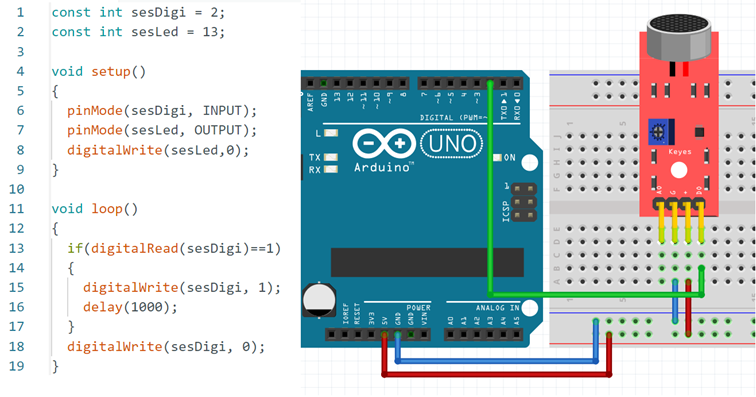
In the microphone, there are two plates close to each other that act as a capacitor. The plate, which is close to the external environment, is flexible and vibrates as sound is applied. This plate moves closer and further away from the fixed plate at the back as a result of vibration. According to this vibration, a voltage occurs at the output of the sensor and this voltage fluctuates according to the sound. This sensor module can give both analog and digital outputs. If the digital output of the module is above a threshold value determined by the potentiometer on the module, it becomes logic 0, if it is below the specified threshold value, it becomes logic 1.
When Visual 2.4 is examined, the following information is reached:
- The pin that says D0 is the digital output.
- The pin that says + is the 5 volt supply.
- The pin that says G is the GND (ground) supply.
- The pin that says A0 is the analog output.
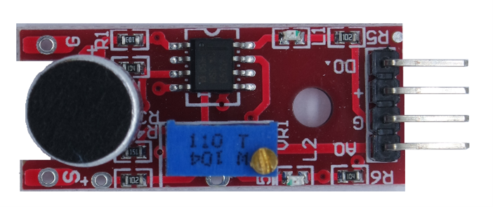
be used as D0 (digital) or A0 (analog) depending on the desired or empty pin status on the microcontroller board.
APPLICATION 1: When the sound of applause is applied with the sound sensor in Visual 2.4, apply the operation that turns on the L LED connected to pin 13 on the microcontroller application card for 1 second, using both the digital output of the sensor and the analog output of the sensor.
Necessary materials
- 1 application board with microcontroller
- 1 x sound sensor module (red one)
- 1 breadboard
- connecting cables
- Step 2: Set the threshold value of the sensor. For this adjustment, connect the (+) pin of your sensor to the +5 volt supply line and the G pin to the GND supply line. Using a screwdriver, turn the potentiometer counterclockwise (to the left) until the L2 LED goes out. After the L2 LED goes out, define the threshold value by turning it counterclockwise or clockwise according to the loudness of the clap. After this identification, the sensor is ready for use.
- Step 2: Write the program in Figure 2.5 and upload it to the microcontroller card. When the circuit diagram is prepared and the clap sound is applied , the L LED on the microcontroller application card will turn on and turn off after 1 second.
¶ 2.2.1.3. Light Level Sensor
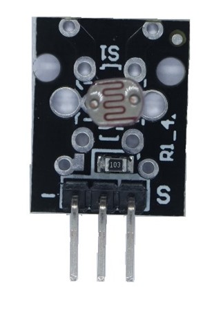
The light level sensor is the sensor whose resistance value changes according to the intensity of light falling on it. Generally, LDR (Light Dependent Resistor) sensor is used to measure light intensity. As the light intensity falling on this sensor increases, the resistance value decreases, but since the LDR does not perform this process linearly, very healthy results cannot be obtained. For this reason, LDR is used at more light-no-light or simpler levels. More advanced sensors can be preferred in this area for sensitive studies. When using the LDR sensor, the connections of the sensor to the microcontroller system should be done as in Figure 2.6.
¶ 2.2.1.4. Distance Sensor
The distance sensor is the structure that allows measuring the distance of the sensor to a certain object. In the distance sensor, measurement is usually carried out by making use of light and sound information. Laser diode or infrared LED are used in illuminated systems. In sound systems, ultrasonic sounds are used. In both methods, the information is sent for a short time and is immediately interrupted. Afterwards, the transmitted information is expected to be reflected back and the time is kept. When the data is returned, the formula Path = Velocity * Time in the path problem is applied. Since the data takes the same distance both on the way and on the way back, the distance between the sensor and the object is calculated by dividing the path information into two.
¶ 2.2.1.5. Gas Sensor
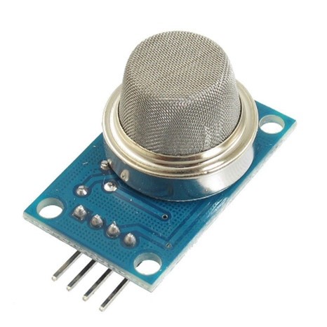
Generally MQ series is widely used in gas sensor. In this series, the sensor is connected and the sensor is expected to warm up. After the sensor heats up, when the wire in the sensor comes into contact with the gas that is sensitive to that gas, it causes a change in the resistance value and returns the analog information. These sensors can be sold individually or as modules. The module version of the sensor has both analog and digital outputs and is ready to use with the circuit with the necessary values for the sensor. If the digital output of the module is above a threshold value determined by the potentiometer on the module, it becomes logic 0, if it is below the specified threshold value, it becomes logic 1. In the non-module version, the circuit in the sensor's document should be applied and resistors with appropriate values should be installed (Figure 2. 7).
MQ-2: When the manufacturer's document of the sensor is examined, it is seen that the R L resistance takes values between 2 KΩ and 20 KΩ according to the density of cigarette smoke, LPG, propane and hydrogen gases in the range of 300 to 10000 ppm .
MQ-3: When the manufacturer's document of the sensor is examined, it is seen that it takes values between 1 MΩ and 8 MΩ according to the alcohol density in the range of 0.04 to 4 mg/L. 200 KΩ should be preferred as the R L resistor.
MQ-4: When the manufacturer's document of the sensor is examined, it is seen that it takes values between 10 KΩ and 60 KΩ according to the natural gas density in the range of 200 to 10000 ppm . 20 KΩ should be preferred as the R L resistance.
MQ-5: When the manufacturer's document of the sensor is examined, it is seen that it takes values between 10 KΩ and 60 KΩ according to the density of LPG, LNG and natural gas in the range of 200 to 10000 ppm . 20 KΩ should be preferred as the R L resistance.
MQ-6: When the manufacturer's document of the sensor is examined, it is seen that it takes values between 10 KΩ and 60 KΩ according to the density of LPG, LGN, isobutane and propane gases in the range of 200 to 10000 ppm . 20 KΩ should be preferred as the R L resistance.
MQ-7: When the manufacturer's document of the sensor is examined, it is seen that it takes values between 2 KΩ and 20 KΩ according to the density of carbon monoxide gas in the range of 20 to 2000 ppm . One of the values of 5 KΩ, 10 KΩ and 47 KΩ should be preferred as the R L resistance.
MQ-9: When the manufacturer's document of the sensor is examined, it is seen that it takes values between 2 KΩ and 20 KΩ depending on the density of combustible gases in the range of 100 to 10000 ppm .
APPLICATION 2: Apply the structure that lights the LED connected to pin 13 on the microcontroller application card when lighter gas is applied with the gas sensor module, and turns off the LED connected to pin 13 when the gas dissipates, using both the digital output of the sensor and the analog output of the sensor.
Necessary materials
- 1 application board with microcontroller
- 1 gas sensor MQ-5 module (blue one)
- 1 breadboard
- connecting cables
- Step 2: Determine the threshold value of the sensor to make the digital adjustments. For this adjustment, connect the (+) pin of your sensor to the +5 volt supply line and the G pin to the GND supply line. Using a screwdriver, turn the potentiometer counterclockwise (to the left) until the L2 LED goes out. Apply lighter fluid after the L2 LED goes out. Define the threshold value by turning it counterclockwise or clockwise depending on the sensitivity of the sensor. After this identification, the sensor is ready for use.
- Step 2: Write the program in the Figure 2.8 and upload it to the microcontroller card. Prepare the circuit diagram and apply the lighter gas to the sensor. The L LED on the microcontroller application card will turn on when gas is detected, and turn off when the gas is cut off.
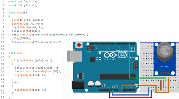
When the program runs for the first time, it is waited for 20 seconds so that the sensor can warm up. When the sensor is ready, LPG gas is applied, when the specified threshold value is exceeded, the gas value is transferred from the analog output of the sensor to the application card with microcontroller . The microcontroller application card transfers this information to the computer via the USB port and reflects the value to the user via the serial monitor.
¶ 2.2.1.6. Flame Sensor
infrared receiver on the flame sensor module is sensitive to light with wavelengths between 760 nm and 1100 nm. This sensor module can give both analog and digital outputs. If the digital output of the module is above a threshold value determined by the potentiometer on the module, it becomes logic 0, if it is below the specified threshold value, it becomes logic 1. When the sensor does not see a flame, it sends 1024 level information from its analog pin and logic 1 from its digital pin. When it sees a flame, it sends a value below 500 from its analog pin and 0 information from its digital pin logically.
When Visual 2.9 is examined, the following information is obtained:
- The pin that says D0 is the digital output.
- The pin that says + is the 5 volt supply.
- The pin that says G is the GND (ground) supply.
- The pin that says A0 is the analog output.
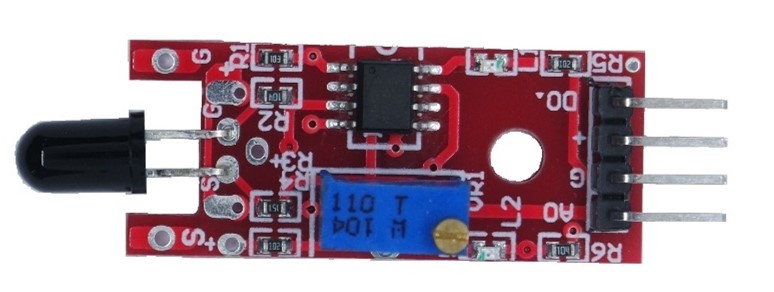
be used as D0 (digital) or A0 (analog) depending on the desired or empty pin status on the microcontroller board.
¶ 2.2.1.7. Flood Sensor
When the structure of the sensor in Visual 2.10 is examined, the water causes the transistor to be driven by short-circuiting the two gray lines. The driven transistor gives an analog output between 0-5 volts and transfers the information read by the sensor to the microcontroller system.
When Visual 2.10 is examined, the following information is obtained:
- The pin that says - is the GND (ground) supply.
- The pin that says + is the 5 volt supply.
- The pin that says S is the analog output.
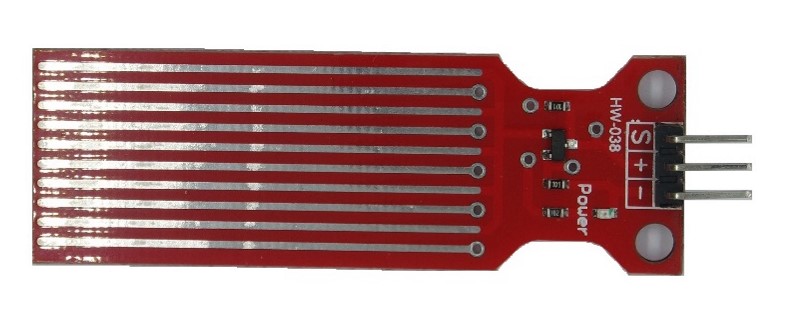
APPLICATION 3: Using the water level sensor in Figure 2.10, apply the operation that turns on and off the LED connected to pin 13 on the microcontroller application card for 100 milliseconds when the conductive liquid level in a glass exceeds 10%.
Necessary materials
- 1 application board with microcontroller
- 1 water level sensor module (red one)
- 1 breadboard
- connecting cables
- Step 2: Download the program in Figure 2.11 to the application card with microcontroller .
- Step: Apply the circuit diagram in Figure 2.11.
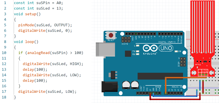
3. Step 2: Submerge the sensor in a glass of water and observe the LED response according to the depth of the water.
¶ 2.2.1.8. Magnetic Field Sensor
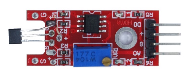
If the structure of the sensor is examined, it is seen that the magnetic field sensor can give both analog and digital outputs. If the digital output of the module is above a threshold value determined by the potentiometer on the module, it becomes logic 0, if it is below the specified threshold value, it becomes logic 1.
When Visual 2.12 is examined, the following information is obtained:
- The pin that says D0 is the digital output.
- The pin that says + is the 5 volt supply.
- The pin that says G is the GND (ground) supply.
- The pin that says A0 is the analog output.
¶ 2.2.2. Actuators (Actators)
An actuator is a type of motor used to control or move a system or mechanism. It is powered by an energy source. This energy source; can be electrical, hydraulic (fluid pressure), pneumatic (air pressure), or thermal (temperature). In other words, actuators are responsible for converting the electrical signal into physical output. Thanks to this physical output, it is possible to inform a user with LEDs, give an audible warning with a buzzer or change the temperature of the environment where the user is located.
¶ 2.2.3. Controllers (Controllers)
Controllers are responsible for collecting data from sensors and providing network connectivity. Controllers can make instant decisions with the data they collect from the sensors or send the data to a more powerful computer for analysis. This powerful computer can be on the same local area network as the controller or in a remote data center.
At the center of microcontrollers is the microprocessor. Microcontroller, Harvard or Von It is the basic structure obtained by creating memory (RAM & ROM) management using one of the Nuemann architectures and connecting the input-output ports. Microprocessor, memory and input-output ports come together to form the microcontroller. Additional features (ADC-Analog Digital Converter-Analog Digital Converter, DAC- Digital Analog Converter-Digital Analog Converter, serial communication port, interrupts, timer and counter) can be added to the microcontroller system. Microcontrollers are small computers that take the written program into ROM memory, compile it on the microprocessor and give outputs according to the purpose of the electronic machine. Microcontrollers have the ability to prepare and control the program to be run, and are designed to run real-time applications.
NodeMCU , ESP32, Raspberry Pi are generally used together in IoT projects . For example, data from sensors can be collected with Arduino, then these data can be processed and visualized with Raspberry Pi.
In general, there are units in the structure of the microcontroller in Figure 2.13. Additional features can be brought to these units according to the purpose of designing the microcontroller.

- MIB (Central Processing Unit): It provides the execution of the program in the ROM memory and its communication with other units.
- RAM ( Random Access Memory / Random Access Memory) Unit: It is the type of memory where the values defined by the user and the operations performed are kept temporarily.
- ROM (Read Only Memory) Unit: It keeps the programs recorded in the microcontrollers so that the system will work as programmed.
- I/O Ports: These ports are used to send the necessary signals to the external environment or to receive the desired signals from the external environment.
- Serial / Parallel Communication Units: Two communication methods, synchronous (SPI, I2C) and asynchronous (USART) are used within the MCU system in serial communication. In the asynchronous communication type, only 2 pins ( Tx , Rx ) are sufficient. In synchronous communication, data sending is required for I2C and the accompanying clock pulse pin is required for SPI, while pins and data sending pins are required as much as the number of hardware to be connected. If the designed system has sufficient number of pins and the distance to transfer data is short, parallel connection type can be preferred. In parallel connection, as many pins as the number of bits of the data line should be used.
- A/D and D/A Converters: A/D converters convert analog signals received from the environment to digital, in other words, binary number system, while D/A converters do the opposite of this process.
- Timer and Counter Unit: It performs the counting and timing tasks in the microcontroller and interrupts when the specified time or number is reached without disturbing the program flow. After the interrupt process is completed, it continues from where it left off in the main program running inside the microcontroller.
- Interrupts: Microcontrollers have as many interrupts as the additional hardware they have. Interrupts are based on the interrupt notifying the microprocessor by completing the desired operation without load on the microprocessor. For example, as soon as data comes from the serial communication channel with the USART method, the serial communication unit in the microcontroller sends an interrupt to the microprocessor and reads the data by informing it that it has received data. The microprocessor, which receives the interrupt information, reads the data from the serial communication unit and continues its operation.
Microcontrollers are also called embedded systems because they hold hardware parts (MIB, RAM, ROM, I/O units, etc.) in their structures. Microcontrollers generally process the environmental data they receive from the sensors in accordance with the purposes of the system they will create. The following should be considered when choosing a microcontroller for a robotics project:
- Having many additional features (serial connection types, timer and counter etc.)
- Cheap and easy to obtain
- Ease of programming
- Lots of resources and libraries
- Microcontroller additional hardware ( shield )
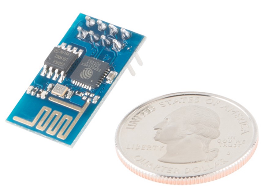
IoT devices, there is a microcontroller in the center and in addition a module that can connect to the Wi - Fi network. In these systems Atmel , Microchip Pic or STM microcontrollers are used. With these microcontrollers , any device connected to the microcontroller can be controlled over the internet by connecting to the home network with the Wi -Fi module from the ESP family (Figure 2.14).
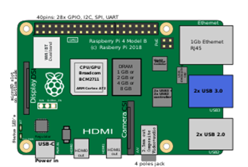
ESP Wi - Fi modules in Figure 2.15, objects can be controlled over the internet without the aforementioned microcontrollers. Systems that have their own Wi -Fi module, such as the Raspberry Pi in Figure 2.14, can also be used for this purpose.
¶ 2.3.1. Microcontroller Circuit Boards Used in Internet of Things Applications
The cards used in the Internet of Things and robotics applications are similar. There are special microcontroller cards developed for these applications. Chief among these are boards such as Arduino UNO, Arduino Wi -Fi, ESP8266, ESP32 and Raspberry Pi.
¶ 2.3.1.1. Arduino UNO Microcontroller Board
Arduino UNO is one of the most preferred models among Arduino boards. It is a microcontroller board suitable for developing robotic applications and internet of things applications. It uses ATmega328P processor as micro controls. It has six analog inputs and 14 input/output pins, six of which use Signal Width Modulation (PWM).
PWM: It is a signal modulation technique used in boards such as Arduino. The principle of switching lies behind the PWM technique. For example, if the PWM pin (needle, foot, leg) used is in the "ON" position, 5V is applied to this pin, and 0V is applied when the pin is in the "OFF" position. In this way, power loss is prevented and digital control units can be controlled more easily. Visual 2.17 shows the structure of Arduino UNO microcontroller circuit board.
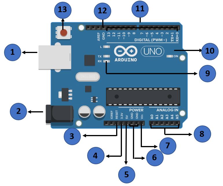
Table 2.1. Terminals and Description of Arduino UNO Microcontroller Circuit Board
| Impression Number | Usage Description |
|---|---|
| 1 | USB cable is the connection input. It is used to communicate data between the computer and the Arduino board. |
| 2 | It is the power input for the Arduino board. |
| 3 | It is the pin input used for resetting the Arduino board. With a button to be connected to this pin, the program uploaded to the Arduino board can be restarted. |
| 4 | It is the supply pin that gives 3.3 Volt output. The components used with the Arduino board work with 3.3 volts and 5 volts. This pin is used for components powered by 3.3 volts. |
| 5 | It is the supply pin that gives 5 Volt output. The components used with the Arduino board work with 3.3 Volts and 5 Volts. This pin is used for components operating with 5 Volts. |
| 6 | GND ( Ground ) - It is the pin used to ground your circuit in Arduino. |
| 7 | Vin can be used to power the Arduino board from an external power source, such as an AC mains power supply. |
| 8 | Arduino has 5 analog pins (A0, A1 ,A 2,A3,A4 and A5). These analog pins read the signal from analog sensor such as humidity and temperature sensor and convert them into a digital value. |
| 9 | TX, RX LEDs; These are LEDs used to monitor data exchange during data sending (TX) and receiving (RX). |
| 10 | It is the LED that should light up when the power input of the Arduino board is connected correctly. If the LED is not lit, it can be thought that there may be a problem with the power connection. |
| 11 | They are PWM pins. Arduino UNO microcontroller board has 14 digital input / output (I/O) pins. These pins are used to read values 0 and 1. Components that can be turned ON and OFF (such as LED, Relay) are connected to the PWM pins indicated as “ ~ ”. |
| 12 | GND ( Ground ) - It is the pin used to ground your circuit in Arduino . By positioning it on the right and left sides of the card, it provides convenience in matching the components to be connected. |
| 13 | By pressing this button, the Arduino board is reset. With the reset process, the program installed in the card is restarted. |
The general features of the Arduino UNO microcontroller board are:
- Easy to connect to computer via USB
- Supporting modes like PWM
- Having a 16MHz microprocessor
- Ability to work directly with power from the USB port
- Have 32 KB USB memory
- Open source interface
Wi -Fi on the Arduino UNO microcontroller board, this board will not have access to the internet. If Arduino UNO is to be used in applications such as the Internet of Things, a Wi -Fi module is absolutely needed to connect to the Internet. Serial Wi -Fi Module and its connectors are shown in Figure 2.18 . By connecting the Arduino UNO and the Serial Wi - Fi Module, the data collected from the sensors are transferred to the internet via the serial Wi -Fi module.
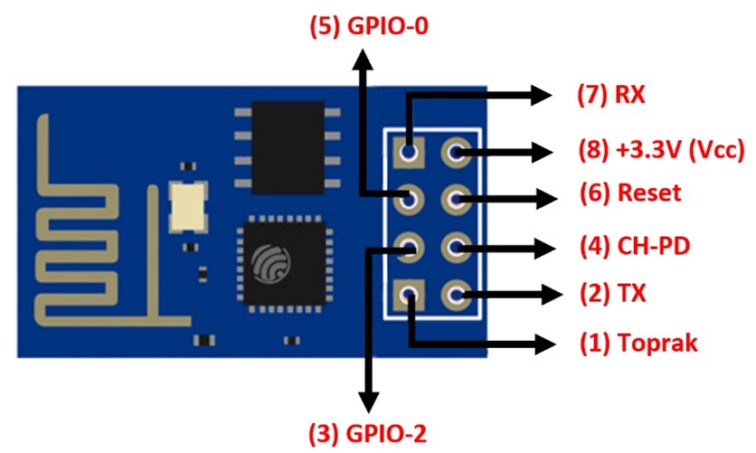
¶ 2.3.1.2. Arduino UNO Wi -Fi Microcontroller Board
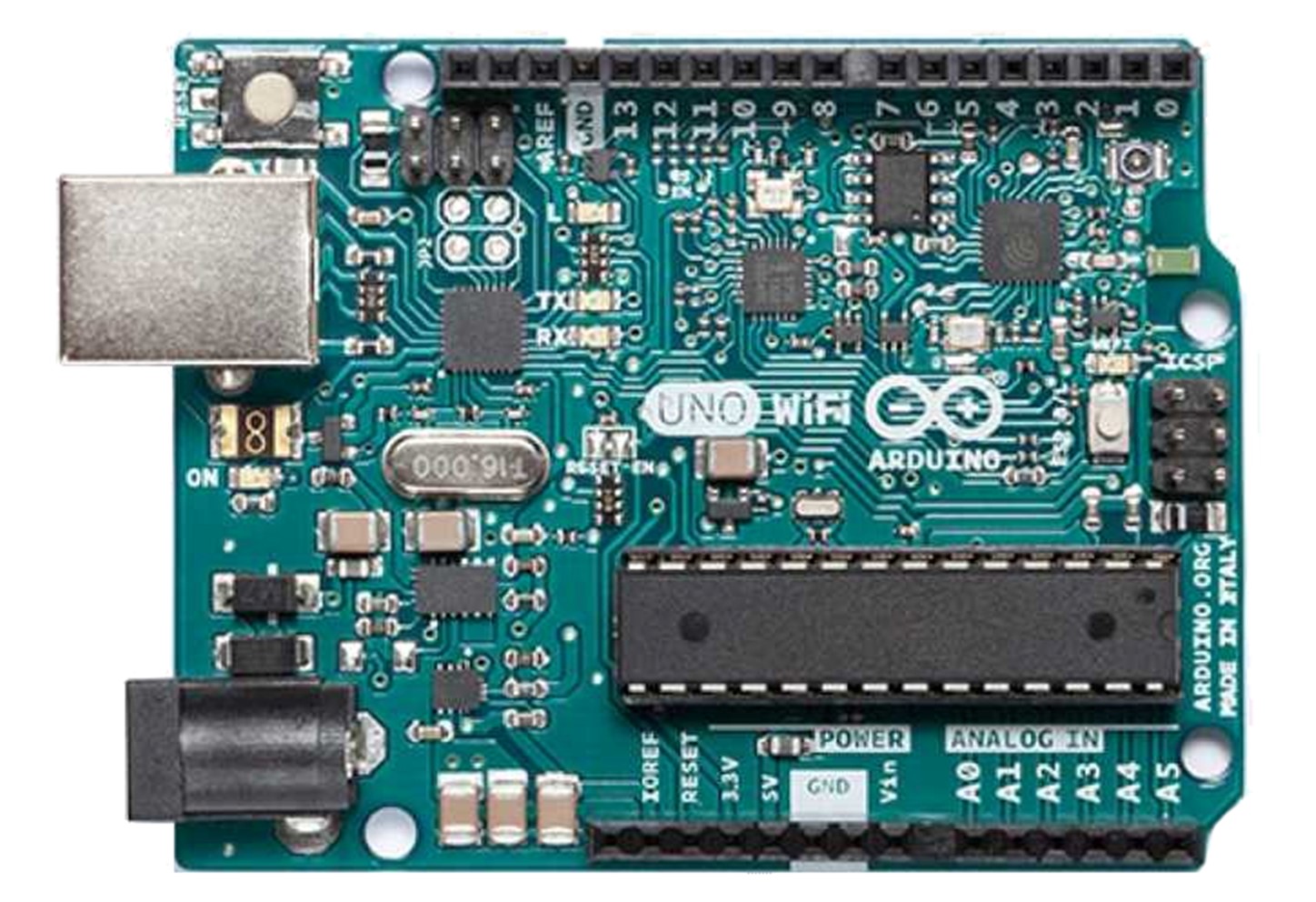
In general, it is the same structure as Arduino UNO. The only difference is that it has an integrated Wi - Fi module. Integrated The Wi -Fi module acts as a standalone access point, supporting the integrated TCP/IP protocol, which can access the Wi -Fi network. Arduino UNO Wi - Fi Module is shown in Visual 2.19. This microcontroller card has internet access thanks to the Wi -Fi module.
¶ 2.3.1.3. NodeMCU Microcontroller Board
NodeMCU (Node MicroController Unit) is an ESP8266 -based microcontroller circuit board that connects and communicates objects with each other in IoT-based applications, and can allow data transfer using the Wi -Fi protocol. NodeMCU is used quite frequently in applications such as the Internet of Things and developed projects, as it has some important features such as GPIO, PWM, ADC. Figure 2.20 shows the NodeMCU microcontroller circuit board structure and connection pins.
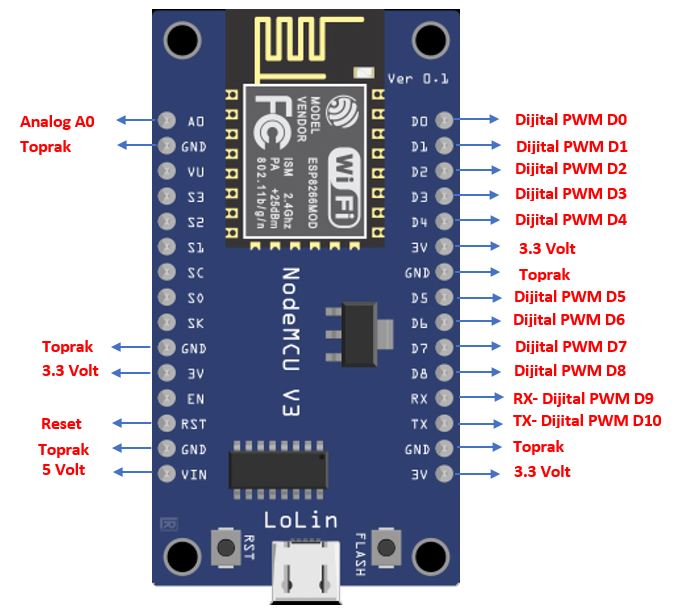
The NodeMCU microcontroller board is easy to use and can be programmed with the Arduino IDE software language. Since it can be easily connected to a computer with a USB cable, it is often preferred in Internet of Things applications. The features of the NodeMCU microcontroller board are shown in Table 2.2.
Table 2.2. Features of NodeMCU Microcontroller Board
| Processor Speed | 80MHz |
| USB Connection Type | MicroUSB |
| Operating Voltage | 3.3 Volts |
| Output Voltage | 4.5 Volts - 10 Volts |
| Flash Memory / SRAM | 4MB / 64KB |
| Digital Input Output Pins | 10 units |
| Analog Pin | 1 Piece |
| Built-in Wi-Fi | 802.11b/g/n |
¶ 2.3.1.4. ESP32 Microcontroller Board
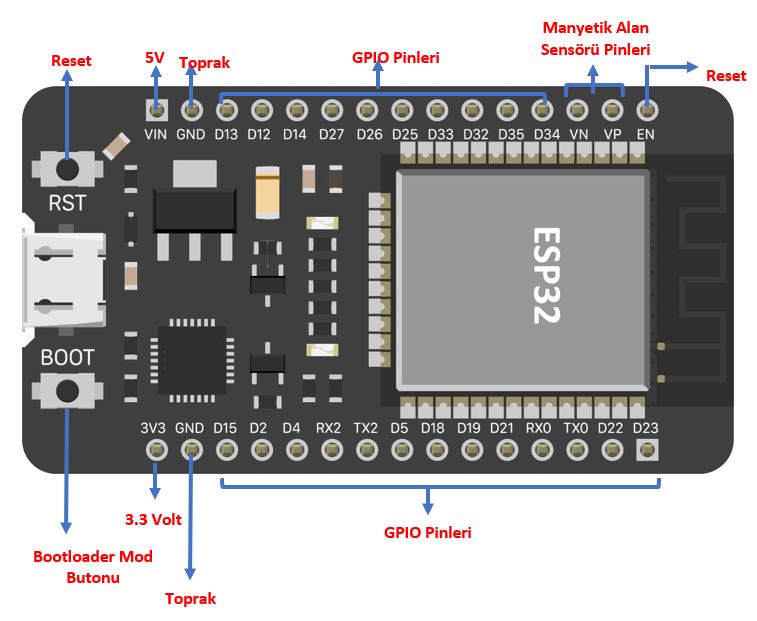
ESP32, integrated on It is a low-energy microcontroller with Wi -Fi and Bluetooth integrated. ESP32 is basically a chip, and the development boards using this chip are called "ESP32" by the manufacturer. Based on the development strategy, it was developed to replace the ESP8266 with a faster microprocessor, memory, Wi -Fi and bluetooth features. Standard models have built-in sensors such as temperature, touch sensor and hall effect (measuring magnetic field) sensor. Features of a standard ESP32 board are listed in Table 2.3. Figure 2.21 shows the structure and pins of the ESP32 microcontroller board.
Table 2.3. Features of ESP32 Microcontroller Board
| Processor Core | 2 |
| Processor Speed | 240MHz |
| Processor Architecture | 32bits |
| Wi-Fi | IEEE802.11 b/g/n |
| Bluetooth | Available |
| Flash / RAM | 16MB / 520KB |
| GPIO Pin | 22 |
There are many brands and models of ESP32 microcontroller development boards produced by different manufacturers. ESP32 card should be selected according to the project to be developed. The features to consider when choosing a card are as follows:
- GPIO numbers (Each GPIO pin supports three types of inputs and outputs. These are analog, digital and internal sensor data.)
- Wi -Fi antenna
- Built-in sensors
- USB memory quantity
ESP32 is frequently used in IoT applications thanks to its features. The usage areas of ESP32 in the field of internet of things are as follows:
- Networking: Connecting devices to routers and communicating data
- Point-to-Point Connection: Direct communication between ESP32s and different devices
- Web Server: Serving as a web server, albeit with limited access
- Data Processing: Processing and computing data from analog or digital sensors
¶ 2.3.1.5. RASPBERRY PI Microcontroller Board
Raspberry Pi is a single board computer (SBC - Single Board Computer) developed to teach simple computer science in schools of developing countries. Paspberry Pi is in high demand for its small size and cheap cost.
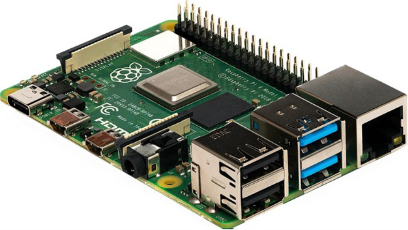
Since Raspberry Pi is a card developed as a simple computer, it does not contain external components such as keyboard, mouse, case. These components are externally attached. It has VideoCore IV GPU graphics processing unit. SD card is used in Raspberry Pi for boot operations and data storage. There are USB 2.0-USB 3.0 ports, HDMI video output, audio output, MIPI camera input, GPIO interface and 5V MicroUSB power input on the board. Raspberry Pi; It supports Raspian, Piora, Snappy Ubuntu Core, Pardus ARM, Arch Linux ARm and Windows 10 IoT Core operating systems. Python, BBC Basic, C and Perl are used as programming languages.
Raspberry Pi board is available in Raspberry Pi 1A+ / 1B+, Raspberry Pi 2B, Raspberry Pi 3A+ / 3B / 3B+, Raspberry Pi 4B, Raspberry Pi Pico, Raspberry Pi Zero, Raspberry Pi Zero W models. These models differ in size, memory, CPU, USB ports, video output, storage unit, GPIO, ethernet and power consumption. Appropriate card selection should be made according to the usage area and the project.
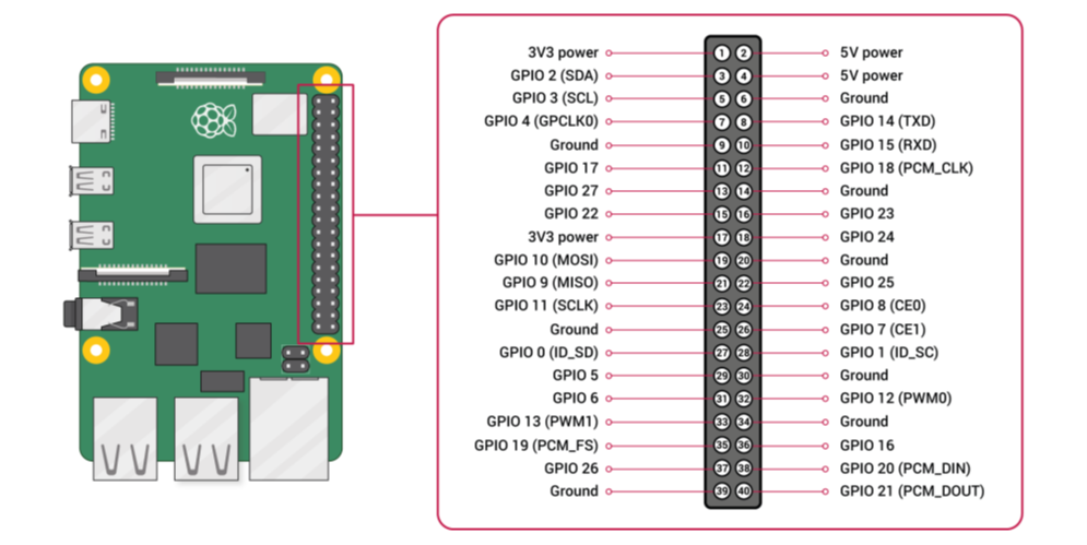
Table: Raspberry Pi variantsy
| Model | CPU | RAÖ | USB | Video Port | Ethernet | GPO Pin | Memory |
|---|---|---|---|---|---|---|---|
| Raspberry Pi 2 | 900 MHz Quad Core | 1 GB | 4 pcs | HDMI | Ethernet | 40 pin | mikroSD kart |
| Raspberry Pi 3 | 1.2 GHz Quad Core | 1 GB | 4 pcs | HDMI | Ethernet, Wi-Fi 802.11n, Bluetooth 4.1 | 40 pin | mikroSD kart |
| Raspberry Pi 3 B+ | 1.2 GHz Quad Core | 1 GB | 4 pcs | HDMI | 2.4 GHz ve 5 GHz IEEE 802.11b/g/n/ AC kablosuz LAN, Bluetooth 4.2 | 40 pin | mikroSD kart |
| Raspberry Pi Zero | 1 GHz Single Core | 512 MB | 1 mikroUSB | Mini HDMI | - | 40 pin | mikroSD kart |
| Raspberry Pi 4 B | 1.5 GHz Quad Core | 2 GB, 4 GB, 8 GB | 2 pcs USB 2.0, 2 pcs USB 3.0 | Mikro HDMI | Gigabit Ethernet | 40 pin | mikroSD kart |
¶ 2.2.4. Connection
Connection in the Internet of Things is generally examined in three types. Connection types are:
- Power Connections: IoT devices must be connected to a power source. This power connection is provided from battery, AC source, external DC source, PoE (over Ethernet), or renewable energy sources.
- Circuit Connections: Sensors and actuators inside the device are connected to the controllers with circuit boards and wires.
- Network connections: IoT devices connect to each other to form small networks. These networks are established with copper, fiber optic cable and wireless media media. Communication takes place with the protocol used according to the media type.
¶ 2.2.5. Analysis (Data Processing)
Data processing is the transformation of raw data collected by sensors into meaningful and usable information. Data processing can take place locally or in the cloud. Analytics is the most important component within the IoT ecosystem.
¶ 2.2.6. User interface
The user interface is a platform where the IoT system and the objects in the system can be controlled and managed. Mobile application, website, desktop application or a hardware design such as button, LCD screen circuit can be used as interface.
¶ 2.2.7. Cloud computing
Cloud computing; It is used to store data, analyze data, access online applications, and provide backup services for personal and corporate use. With the increase in the number and variety of IoT devices, the amount of data that needs to be processed has also increased. As IoT systems grow and become more complex, data processing with controllers and personal computers has become more difficult. For this reason, it has become inevitable to process the increasing data with cloud computing.