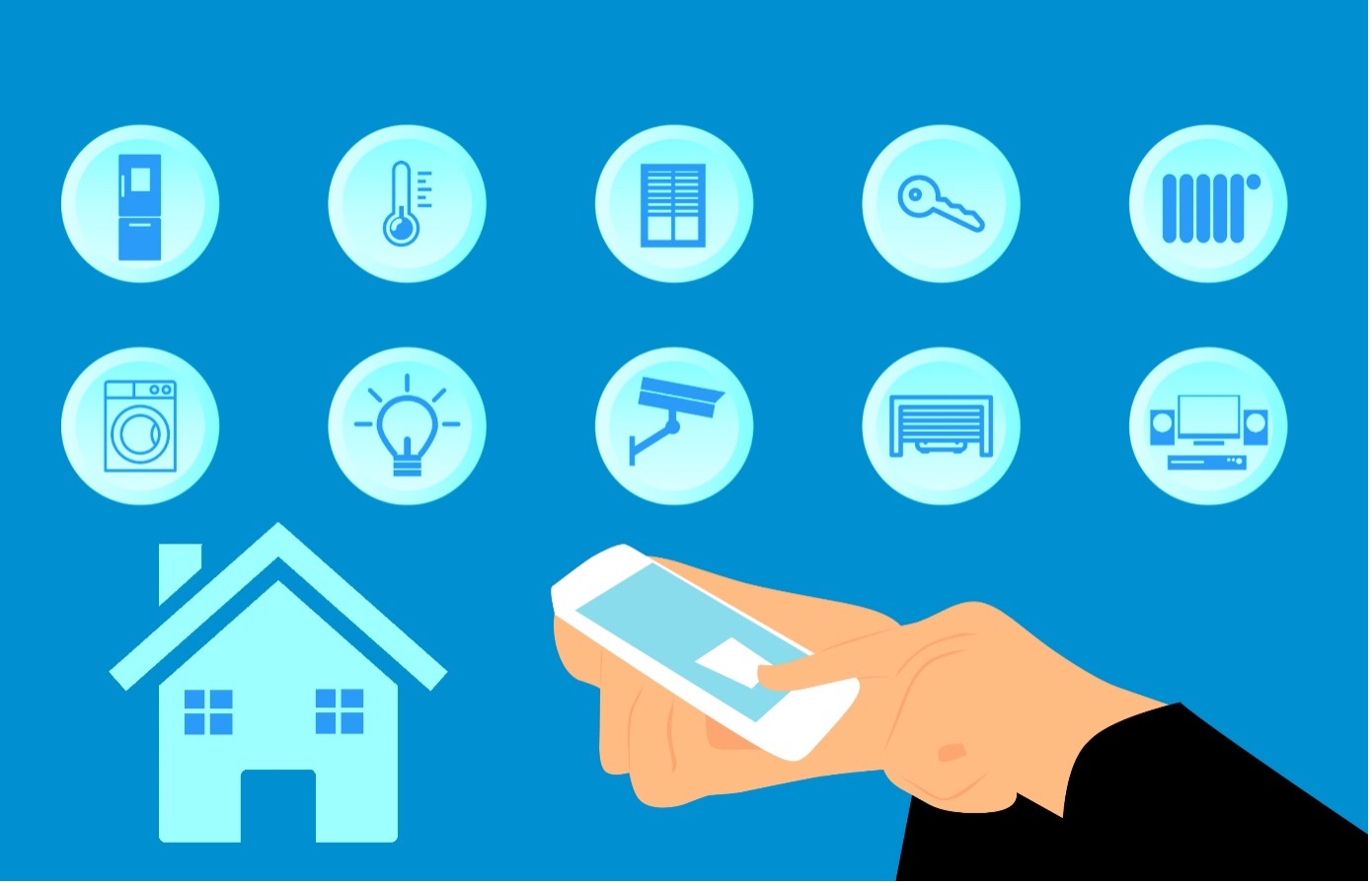
Today, many devices such as smart phones, smart TVs, smart watches are connected to the internet. With the development of mobile networks and the internet, the number and variety of these smart devices are increasing day by day. This increase has made it inevitable for computers connected to each other to exchange data with devices and objects connected to each other. Connecting everything imaginable, from cars to clothes, from digital clocks to electricity and water meters, from coffee machines to soccer balls, from smart homes to smart cities, has turned into the Internet of Things (Figure 1.1).
The Internet of Things ( IoT ) is a network where millions of smart devices and sensors connected to the Internet communicate with certain protocols. The concept of the Internet of Things ( IoT ) was first introduced in 1999 by Kevin Ashton in a presentation on RFID technologies. In the Internet of Things, there may also be situations where smart devices are not connected to the Internet. Examples of this situation are RFID, RTLS and Beacon etc. technologies can be given to produce information with some devices.
¶ 1.1. Areas where the Internet of Things is used
In this period when everything has become smart, there is no area where the Internet of Things has not entered (Figure 1.3). The areas where the Internet of Things is most used are:
|
• Smart home building automation • smart city • Industry • Health • energy systems • Transport • Meteorology • Agriculture and greenhouse cultivation • farming • disaster management • Environment • Media • Marketing • Advertising • Logistics • military and security • Education • Wearable technologies • Government Policy |

|
¶ 1.2. Why connect the objects
The Internet was born as a connectivity solution that connects local networks so they can exchange information. It is a form of communication between people. The possibility of linking objects opens up a new paradigm in communication, because objects need to generate the information they exchange and basically act based on certain parameters.
Watering our garden has hitherto been a manual job. Even if we install sprinklers, it is up to us to turn them on every time we need to water them, thinking that the soil has enough moisture. We can program a timer to start and stop watering without manual intervention, but it will start and stop even if it rains.
An IoT -based irrigation solution has at least the following features:
- Moisture sensors for soil moisture monitoring.
- A rain sensor.
- A transmission medium for transmitting data produced by sensors.
- A computing unit for processing data produced by sensors.
- A mechanism for activating/deactivating irrigation sprinklers.
The points mentioned constitute a highly efficient solution: the sprinkler will deliver water to the ground only when the sensor data meets the predetermined conditions of the processing unit (basically soil moisture parameters are below acceptable and no rain is falling). But that's not all. The IoT solution is an important source of information. From the data provided by the sensors, irrigation, precipitation cycles, changes in soil moisture, etc. It is possible to have statistics about
¶ 1.3. Products Using the Internet of Things
There are many products that use the Internet of Things. These products are used in various industrial areas, homes, hospitals, vehicles, greenhouses, etc. used in places.
- Smart Things: It is a product used for smart home systems. It enables the automation and management of electronic appliances, heating and lighting systems in the house with a single application.
- OttoLock Smart Lock: It is a product used for keyless automatic entry-exit to homes and workplaces. It provides the opportunity to lock the doors of the home and workplace via mobile phone, to define entry permission to the home and workplace for the guests who come while they are away from the home and workplace, and to track who enters and exits the home and workplace from the mobile phone.
- HAPIfork: It is a smart fork designed for people who want to improve their health, lose weight or slow down their eating speed. It helps to change the eating behavior.
- Solar Curtain: It is a curtain that allows electricity to be produced with solar energy. With the mobile application, remote access to the curtain can be achieved. In fact, the instant, weekly and annual report of the electricity produced can be followed.
- MiCoach Soccer Ball: The speed, acceleration, strike intensity, round-trip trajectory of the hit ball and the spin data of the ball are tracked instantly with the mobile application.
- iBeat Heart Watch: It is a smart watch that aims to save lives by noticing a heart attack. It constantly checks the person's heart rhythm irregularities and blood circulation. When an abnormal situation occurs, it automatically notifies everyone, including emergency services and acquaintances.
- Dropcam: Allows monitoring of cameras installed in homes and offices via mobile device or computer.
- family Hub Refrigerator: It has a shopping list preparation and ordering feature. In addition, while you are at the market, you can check the missing products in the refrigerator via the mobile application and shop according to your needs.
- Edyn: It gives suggestions on which crops should be planted and how the soil should be irrigated in gardens and fields.
- Smart T-Shirt: It enables the person to have information about his/her performance by reading biological and physiological information. It collects data such as heart rate, stress level, breathing and exhalation of the player during the match.
¶ 1.4. Internet of Things Infrastructure
Different vertical markets determine the type and implementation of an IoT solution. For example, a solution for the oil industry will require a communications infrastructure such as satellite communications that provides wide geographic coverage. In contrast, a home security system can operate with a local communications infrastructure (a private network), which requires greater security and reliability.
| Satellite | Cellular | LPWA | Dedicated local network | Shared local network |
|---|---|---|---|---|
| 2G | Sigfox | WiFi | WiFi | |
| 3G | LoRa | ZigBee | Bluetooth | |
| 4G | NB-IoT | RF-Mesh | ||
| Extensive coverage | Extensive coverage | Extensive coverage | Local coverage | Local coverage |
The communication infrastructure of the Internet of Things can be as follows:
- Satellite: Satellites located at an altitude of approximately 30,000 kilometers in Earth orbit provide communication services.
- Cellular: This is referred to as mobile broadband, which is an Internet service usually provided through the cellular infrastructure.
- LPWA (Low Power Wide Area): is a low power network that provides wide coverage. Sigfox , LoRa and NB- IoT are standards specifically for IoT with the common feature of providing communication over a wide range, at low speed, and at a lower cost than other solutions such as satellite .
- Private local area network: uses high-level protocols for wireless communication that do not require wide coverage but allow a high degree of security.
- Shared local network: when security is not paramount (although it always is, as we will see later), this network provides effective connectivity at a low cost.
Energy Management
When we talk about IoT solutions, energy plays a fundamental role. Different markets require different solutions, and each solution has its own power requirement.
The oil industry implements IoT solutions in areas far from city centers. It is very important to consider that devices have guaranteed power for a long time (usually long-lasting batteries).
On the contrary, the energy in the assembly line of the automotive industry will be absolutely guaranteed and there will be no problem for the IoT solution.
Data management and migration
At this point, it is clear that telecommunications infrastructure is key to exchanging data for an Internet of Things solution. The predicted exponential growth in the number of connected devices in the coming years will generate a database tsunami of data through communication systems.
Bits and Bytes
The unit of measurement in a binary-based data system (such as those used to encode information in computer systems) is a bit (binary. digit) . A bit can only have two values: 0 and 1. A byte is the minimum unit of information, which is an 8-bit string.
The International Organization for Standardization (ISO) and the International Electrotechnical Commission (IEC) have defined a standard for prefixing binary-based data volumes. However, the prefixes of the International System are the most used to represent volumes of data:
| Prefix | Prefix + “byte” | Symbol | Factor and value |
|---|---|---|---|
| byte | B | 100 = 1 | |
| kilo | kilobyte | kB | 103 = 1.000 |
| mega | megabyte | MB | 106 = 1.000.000 |
| giga | gigabyte | GB | 109 = 1.000.000.000 |
| tera | terabyte | TB | 1012 = 1.000.000.000.000 |
| peta | petabyte | PB | 1015 = 1.000.000.000.000.000 |
| exa | exabyte | EB | 1018 = 1.000.000.000.000.000.000 |
| zetta | zettabyte | ZB | 1021 = 1.000.000.000.000.000.000.000 |
| yotta | yottabyte | YB | 1024 = 1.000.000.000.000.000.000.000.000 |
Let's turn this data into reality. If we measure what is happening on the Internet for one minute, what will we find?:
- 400,000 tweets on Twitter.
- 4.5 million posts on Facebook.
- 50,000 photos have been uploaded to Instagram.
- 6.5 million searches were made on Google.
- 15 million ads were viewed.
- 150 hours of video uploaded to Youtube.
- 48,000 hours of music streamed.
- 240,000 apps downloaded.
- 42 million instant messages were sent.
In just one minute, more than 2,000 terabytes of information circulate on the Internet.
¶ 1.5. Advantages and Disadvantages of the Internet of Things
The advantages of the Internet of Things are:
- It improves the quality of life of individuals.
- It saves time and money.
- It provides easy collection of more information.
- It helps to make better decisions.
- It enables the production to be more efficient in the industry.
- It provides more income.
- It makes it easy to monitor business processes.
- It provides greater customer satisfaction.
The disadvantages of the Internet of Things are:
- The privacy risk increases as data is transmitted.
- The risk of security vulnerabilities increases.
- The probability of failure increases in very complex systems.
- It puts personal privacy at risk.
- The amount of data that needs to be stored increases.
¶ 1.6. IoT Basic Circuit Elements
Basic circuit elements are used to connect to the Internet and to control many objects in the environment over the Internet.
¶ 1.6.1. Resistance
The resistance to electric current is called resistance. The resistor symbol is the letter "R". The unit of resistance is Ω (Ohm). The values of the resistors are read by using the resistor color codes in Figure 1.4.
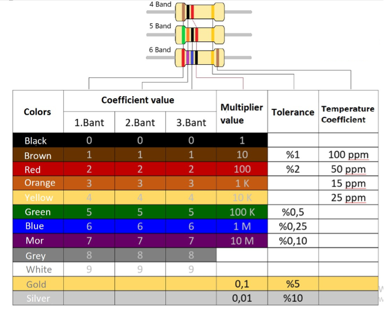
When the resistors are examined, it is seen that the tolerance is positioned separately at the end. In this way, reverse reading situation does not occur in the resistors. When the resistance values are calculated, the following results are obtained:
- In the 4-band resistor, the first two bands are the coefficient, the third band is the multiplier and the last band is the tolerance.
- In the 5-band resistor, the first three bands are the coefficient, the fourth band is the multiplier and the last band is the tolerance.
- The band resistance is the same as the 5 band resistance and the temperature coefficient comes next to the tolerance.
¶ 1.6.2. LED
LEDs are diodes that emit light when current flows through them. They also act as zener diodes by dropping a constant voltage across them . LEDs have different voltage drops according to their colours, but usually 2 V is assumed, and calculations are based on 2 V 20 mA (milliAmps).
Voltage drops according to LED colors are given in Figure 1.5. In LEDs, the long leg is the Anode and the short leg is the Cathode .
| LED Colors | Required Voltage to LED | Current Required to LED |
| Red | 1.5-2.5V | 10 - 20 mA |
| Green | 2.2-3.3V | 10 - 20 mA |
| Blue | 3.3-4.5V | 15 - 30 mA |
| Yellow | 1.8-2.8V | 10 - 20 mA |
| Wite-Ultraviolet | 3.3-4.5V | 15 - 30 mA |
Figure 1.5: Voltage and current values needed according to LED colors
The values here are average values. Values should be calculated from the documentation of the purchased LED. Source Voltage = Resistor Voltage + LED Voltage formula is used to calculate the resistor to be installed before the LED.
¶ 1.6.3. Buzzer
There are two types of buzzer , active (circuited) and passive (circuited ) .
- Active (Circuit) Buzzer: The buzzer has a circuit tuned for a clean sound at a single frequency. This type of buzzer produces a steady sound when a signal is sent to the (+) leg from the microcontroller. The sound of these buzzers can be heard mostly in the overload warning of elevators or in the distance feedback of cars when parking.
- Passive (Disabled) Buzzer: In order to hear the sound of the buzzer, it can make a sound when a signal is sent in a certain frequency range. As the transmitted frequency is changed, it can change the sound and make it ring according to the note information.
Active buzzer can be operated with any pin, while passive buzzer can be operated using PWM method.
¶ 1.6.4. Transistor
The transistor is the switching element that provides the control of high electrical loads with small electrical signals. The transistor usually consists of three legs. These legs; It is called base ( bayz - B ), emitter ( emitter - E ) and collector (collector - C ). There are two types of transistors, NPN and PNP.
NPN: With the small voltage applied to the bayz leg, it allows high voltages to flow between the collector and the emitter . When the voltage applied to the Bayz leg is interrupted , the connection between the collector and the emitter is interrupted.
PNP: When no signal is applied on the base leg , it allows high voltage to flow between the emitter and the collector, while when a low voltage is applied on the base leg, the connection between the emitter and the collector is cut.
¶ 1.6.5. Relay
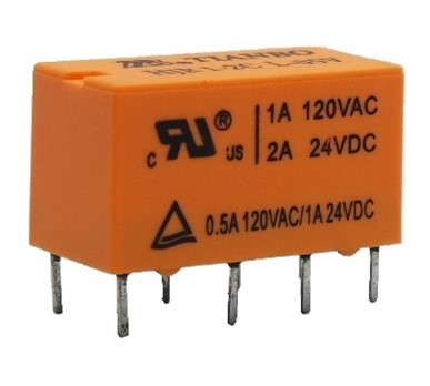
The relay is a structure that contains a coil for magnetization and COM, a normally closed switch and a normally open switch (Figure 1.6). When no current is applied to the coil pins, the NC (Normal Close-Normally Closed) pin is in contact with the COM (common) end. The NO (Normal Open-Normally Open) pin is separate from the COM lead. As a result of the voltage applied to the coil legs of the relay, the current passing through the coil magnetizes the coil and pulls the COM terminal towards itself. After this process, the COM pin leaves the NC and contacts the NO pin. Due to this structure, small voltages and very large voltages can be controlled by isolating microcontroller systems from high voltage systems. All electrical equipment in homes can be controlled with relays. High voltage connections in houses are made using COM, NC and NO pins.
¶ 1.6.6. Button
The button is a circuit element that provides a connection between the two pins 1 and 2 when the (A) button on it is pressed, and cuts the connection between the two pins when the (A) button is pressed, and returns to its original position (Figure 1.7).
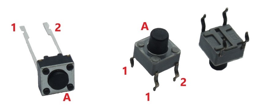
There are two-pin and four-pin versions of the button. In four-pin buttons, two pins that are close to each other show the feature of a button, while two pins that are far from each other are interconnected (Short Circuit). In this way, the button feature is seen between pins 1 and pin 2.
¶ 1.6.7. Key
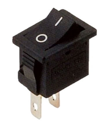
There are two types of switches, limit switches and on-off switches.
- Limit Switch: When no pressure is applied to the contact surface, the NC and COM terminals are short-circuited, NO open. When pressure is applied to the contact surface, the switch inside short-circuits COM and NO , opening the NC . When pressure is released on the contact surface, the switch returns to its original position. When the working structure is examined, it is seen that the switches resemble relays.
- On-Off Switch: This switch is the type of switch that changes position after applying pressure and maintains its position even after the application of pressure ends. The switch needs to be pressed again to return it to its original position. In the “1” position, this switch creates a short circuit between the two pins and allows current to flow, while in the “0” position it disconnects the two pins and breaks the line.
¶ 1.6.8. Breadboard
Breadboard is an element needed to easily assemble the components to be used in the circuit. Thanks to the breadboard , there is no need to solder the circuit elements. This provides the opportunity to reuse the elements and easily change the circuit design wherever desired. Breadboards are available in different sizes in the market. It is important to choose the most suitable breadboard according to the circuit design .
The point to be considered when using breadboard is the vertical and horizontal stripes.

When the breadboard in Figure 1.9 is examined, the area shown in red is called the bus strip. The bus strip is generally used for power supplies. The bus strip is transmitting vertically. The “+” and “-” labels found here are not binding, but they are labeled as “+” and “-“, as the most needed connections in the circuits made. The area shown in orange is called the socket strip and is used to plug in components in the circuit. The middle part, shown in blue, is called the integrated region, and it cuts the breadboard in half, breaking the conduction between the left and right parts of the breadboard. In other words, socket strips consist of five horizontal pins.
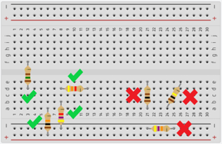
When placing the elements on the breadboard, attention should be paid to the bus strip and socket strip. Example layouts should be as in Figure 1.10. Bus strip and socket strip connections were not taken into consideration in incorrect placements. Since the current to be applied will choose the easiest way, the resistor connections will have no effect or effect on the circuit. In another faulty connection, cross connections are not preferred because they make it difficult to read the circuit.
